
Have you ever wondered how the electricity powering your home or business seamlessly transitions from the power grid to the various appliances you use? It’s a complex dance of energy, made possible by the intricate network of wires and components that make up an electrical system. One crucial element within this network is the 3-phase electrical system, a core concept for industrial and commercial applications. At the heart of understanding this system lies the ability to decipher the 3-phase forward and reverse wiring diagrams, a skill that can empower you with greater control over your electrical setup.

Image: www.pinterest.com
Understanding the nuances of these wiring diagrams goes beyond just technical know-how; it opens the door to a deeper understanding of how power flows and how you can optimize its use. This guide will embark on an exploration of 3-phase forward and reverse wiring diagrams, unraveling the complexities and equipping you with the knowledge to navigate this fundamental aspect of electrical systems.
Delving into the World of 3-Phase Forward and Reverse Wiring Diagrams
Before diving into the intricacies of wiring diagrams, it’s important to grasp the fundamentals of 3-phase electrical systems. Imagine three distinct electrical circuits operating in synchronization, each generating alternating current (AC) but offset from one another by a precise 120 degrees. This offset, known as the phase shift, creates a balanced flow of power, ensuring a smoother and more efficient energy delivery compared to single-phase systems. This becomes critical in industrial applications with large motors and machinery, requiring substantial power for operation.
Now let’s delve into the heart of the matter: 3-phase forward and reverse wiring diagrams. Essentially, they are visual representations of the wiring configuration within a 3-phase system. The wiring diagram serves as a blueprint, depicting the connection between the power source (usually a transformer) and the electrical load (such as a motor or a piece of equipment).
The key differentiator lies in the direction of current flow. A forward wiring diagram illustrates the current flowing in the ‘intended’ direction, while a reverse wiring diagram shows the current flow in the opposite direction. Here’s where things get interesting; these two configurations affect the direction of rotation of a 3-phase motor. This principle is essential in applications like cranes, conveyors, and even fans, where precise control over the direction of rotation is paramount.
Understanding the Components of a 3-Phase Wiring Diagram
To navigate these diagrams effectively, it’s essential to familiarize yourself with the key components:
- Power Source: This is typically a transformer, responsible for stepping down the high voltage electricity from the power grid to a usable voltage for the 3-phase system.
- Phase Conductors (Lines): These are the three wires carrying the AC current from the power source to the load. Each conductor represents a distinct phase of the 3-phase system.
- Neutral Conductor: This wire provides a return path for current to flow back to the power source, ensuring a complete electrical circuit.
- Load: This represents the actual device consuming the electrical power, like a motor, heating element, or a lighting fixture.
Decoding the Anatomy of a 3-Phase Wiring Diagram
To decipher a 3-phase forward and reverse wiring diagram, here’s a step-by-step guide:
-
Identify the Power Source: Look for the symbol representing the transformer, often depicted as a circle with an “X” inside.
-
Locate the Phase Conductors (Lines): These are usually labeled with “L1,” “L2,” and “L3,” indicating the phases. Each line originates from the transformer and extends towards the load.
-
Trace the Neutral Conductor: This wire is often labeled “N” and connects the power source to the load.
-
Examine the Connections to the Load: Observe how the phase conductors and the neutral conductor are connected to the load. This connection configuration determines the direction of current flow and ultimately the rotation of a motor.
-
Compare Forward and Reverse Diagrams: The crucial difference between forward and reverse diagrams lies in the sequence of connections. For instance, in a forward connection, L1 might be connected to terminal A of the motor, L2 to terminal B, and L3 to terminal C. In a reverse connection, the sequence could be switched, for example, L1 to terminal C, L2 to terminal A, and L3 to terminal B.
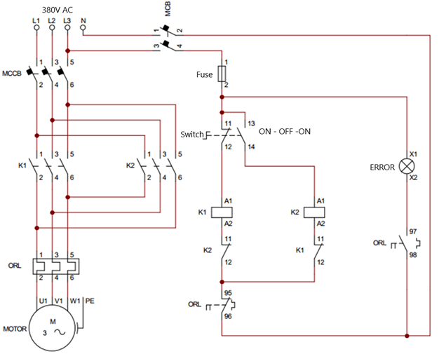
Image: www.hotzxgirl.com
Practical Applications of 3-Phase Forward and Reverse Wiring:
The ability to switch between forward and reverse wiring diagrams opens the door to a world of possibilities; here are some key applications:
-
Motor Control: For applications requiring the direction of motor rotation to be controlled, such as conveyors, cranes, and mixing machines, 3-phase forward and reverse wiring plays a pivotal role.
-
Directional Lighting: This is particularly applicable in industrial or commercial environments using large lighting systems. Switching between forward and reverse wiring can change the direction of light beam, allowing for greater control and optimization.
-
Variable Speed Drives: These systems often rely on inverters to control the speed of motors. Understanding 3-phase wiring diagrams enables efficient integration and control of the inverter for precise motor speed adjustment.
Expert Insights on 3-Phase Forward and Reverse Wiring Diagrams
When it comes to working with electrical systems, consulting experts is essential. Seasoned electricians and engineers can provide invaluable guidance on interpreting wiring diagrams and ensuring safe and effective implementation. Here are some critical tips:
-
Always Double-Check: Before working with any electrical installation, meticulously verify the wiring diagram. It’s crucial to ensure that the diagram accurately reflects the layout of the electrical system and that the connections are correctly identified.
-
Seek Professional Guidance: If you’re unsure about any aspect of the wiring process, don’t hesitate to seek professional assistance. They can help you navigate complex wiring scenarios and ensure the safety of the installation.
3 Phase Forward And Reverse Wiring Diagram Pdf
Conclusion: Mastering the Power of 3-Phase Forward and Reverse Wiring Diagrams
Understanding 3-phase forward and reverse wiring diagrams equips you with a powerful tool to manage and optimize electrical systems. Mastering these diagrams allows you to control the direction of motor rotation, make insightful adjustments to lighting setups, and implement intricate variable speed drive systems. The journey of understanding these diagrams may seem intricate at first, but the rewards of gaining this knowledge can significantly benefit your electrical projects. Remember, always prioritize safety, seek professional guidance when needed, and keep an open mind as you explore the fascinating world of 3-phase electrical systems.


