
Picture this: a bustling factory floor, machines whirring to life, and a team of skilled workers diligently assembling products. Yet, behind the scenes, unseen but essential, lies a network of electrical systems meticulously designed to power these operations. At the heart of this network often sits the Square D motor starter, a vital component for safely controlling and protecting electric motors.

Image: annawiringdiagram.com
Understanding the wiring diagram of a Square D motor starter is crucial for anyone who interacts with these machines, be it electricians, maintenance technicians, or engineers. This diagram serves as a blueprint, guiding the user through the intricate connections within the starter, ensuring proper installation, troubleshooting, and operational efficiency. In this comprehensive guide, we’ll delve into the anatomy of a Square D motor starter wiring diagram, providing you with a clear roadmap to navigate its complex pathways.
The Essence of Motor Starters: Ensuring Safety and Control
Before diving into the intricacies of the wiring diagram, it’s essential to grasp the fundamental role of a motor starter in any electrical system. In essence, a motor starter acts as a gatekeeper, controlling the flow of electrical power to the motor, ensuring safe and controlled operation. Think of it as a traffic light for electrical current — green for go, red for stop, and yellow for caution.
Motor starters are vital for several critical reasons:
- Safety First: By providing a controlled path for electrical current, motor starters prevent overloading, short circuits, and other potentially hazardous conditions. Imagine the chaos if a large motor suddenly bursts to life without regulation!
- Smooth Startup: When a motor starts, it draws a significant amount of current, often exceeding the normal operating load. Motor starters manage this surge by limiting the initial current draw, ensuring a smoother startup and minimizing strain on the motor and electrical system.
- Enhanced Control: Motor starters allow for the control of the motor’s speed and direction, providing flexibility in various applications. This makes them suitable for a wide range of industrial processes, from conveyor belts to pumps and more.
- Protection Mechanisms: Square D motor starters are equipped with built-in safety features such as overload relays and thermal protectors that automatically disconnect the motor if it exceeds safe operating limits. This prevents motor damage and potential fires, ensuring the safety of personnel and equipment.
Deconstructing the Square D Motor Starter Wiring Diagram: A Visual Journey
The wiring diagram, often depicted as a complex web of lines and symbols, is the key to unlocking the mysteries of the Square D motor starter. Let’s break down the components of this diagram into digestible steps:
1. Identifying the Key Components: Unveiling the Starter’s Anatomy
Before we start tracing the wires, it’s crucial to know the components that make up a typical Square D motor starter. These components, along with their functions, are usually clearly labeled on the wiring diagram:
- Control Circuit: This circuit acts as the brain of the starter, processing external commands and initiating the motor’s operation. It typically includes elements like pushbuttons for starting, stopping, and reversing the motor.
- Power Circuit: Carrying the heavy-duty power supply to the motor, this circuit directly connects the power source to the motor through the motor starter’s contactors.
- Contactors: These are electromagnetic switches that act as the “on” and “off” switches for motor operation. When energized, the contactors close, allowing power to flow to the motor. They are typically controlled by the control circuit.
- Overload Relay: This device, often integrated into the contactor itself, monitors the motor’s current flow. If the current exceeds pre-set limits, the overload relay trips, opening the circuit and preventing motor damage.
- Thermal Protector: Located within the motor itself, this device senses the motor’s internal temperature. Similar to the overload relay, it trips and opens the circuit if the motor overheats, protecting it from damage.
- Control Relay: These relays, typically found within the control circuit, are used to perform various functions, such as reversing the motor, controlling the motor’s speed, or initiating other safety measures.
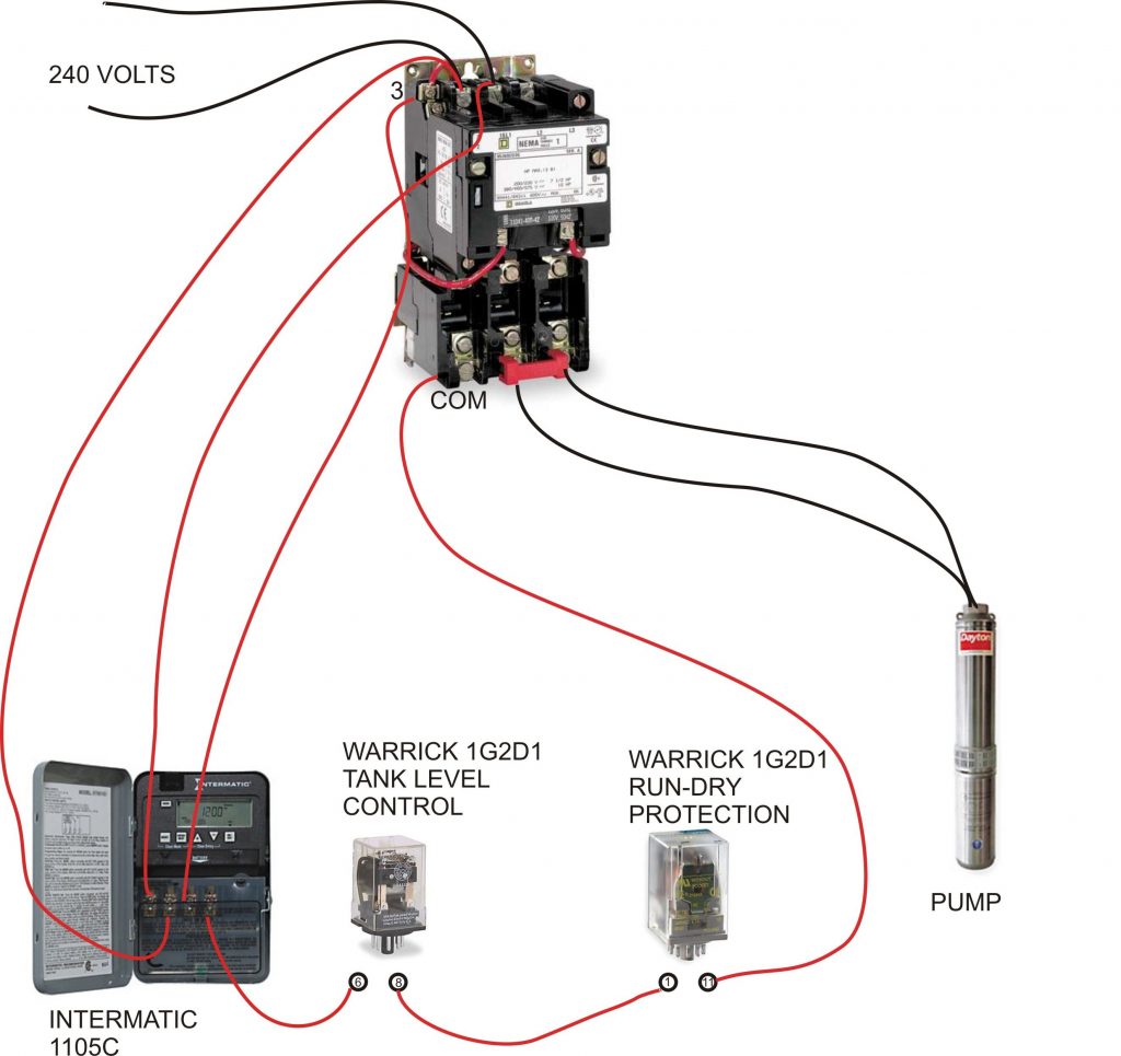
Image: fixenginemarjorie.z21.web.core.windows.net
2. Tracing the Lines: Unleashing the Flow of Power
The wiring diagram acts as a visual map that guides you through the electrical paths within the motor starter. Each wire is represented by a single line on the diagram, with each line indicating a specific connection. The direction of the power flow is usually indicated by arrows on the diagram.
By following the lines, you can trace the connections from the power source to the motor, through the contactors, and to the various control components. Observe the relationships between the different components and how they work together to control the motor’s operation.
3. Unraveling the Symbols: Deciphering the Language of the Diagram
The wiring diagram employs a standardized set of symbols to represent various electrical components. Recognizing these symbols is essential for interpreting the diagram correctly.
- Circuits: Electrical circuits are generally shown as lines with arrows indicating the direction of power flow.
- Contactors: These are represented by a rectangle with a coil inside, indicating the electromagnet that controls the opening and closing of the contacts.
- Pushbuttons: These are represented by a circle with a “NO” (Normally Open) or “NC” (Normally Closed) designation, indicating the state of the contact when the button is not pressed.
- Relays: These are represented by a similar symbol to contactors but typically have multiple contacts controlled by a single coil.
- Fuses: These are represented by a zigzag line with a break in the middle to represent the fusible element that breaks when excessive current flows.
- Motor: The motor is typically represented by a simplified diagram of a motor with a stator and rotor.
Navigating the Square D Motor Starter Wiring Diagram: Practical Tips
Mastering the wiring diagram of a Square D motor starter doesn’t have to be an intimidating task. Here are some practical tips to make the process smoother:
- Start with the Basics: Before diving into complex diagrams, familiarize yourself with the fundamental components of a motor starter and their functions.
- Focus on the Control Circuit: The control circuit is the heart of the starter; understand how it receives input from pushbuttons or other control devices and uses relays to activate the contactors.
- Trace the Power Flow: Start at the power source and follow the flow of electricity through the diagram, noting how it reaches the motor and passes through the safety devices.
- Use a Flashlight or Electric Tester: When working with live equipment, always exercise caution. Use a flashlight or electric tester to visually verify connections and ensure proper wiring.
- Practice, Practice, Practice: The more you study and work with these diagrams, the more familiar you will become with the symbols, connections, and overall operation of a Square D motor starter.
Embracing the Future of Motor Control: Smart Starters and Advanced Technologies
The realm of motor control is constantly evolving, with innovative technologies promising greater efficiency and automation. Square D, a leading provider of electrical solutions, is at the forefront of this evolution, incorporating advanced features into their motor starters:
- Smart Starters: These intelligent devices utilize built-in sensors and data analysis to optimize motor performance, reducing energy consumption and maximizing efficiency. They can even provide predictive maintenance alerts, minimizing downtime and operational costs.
- Variable Frequency Drives (VFDs): Using VFDs, Square D starters can precisely control the speed of electric motors, allowing for more efficient operation and reduced energy usage in various applications.
- Wireless Monitoring: Square D offers wireless communication capabilities for their motor starters, enabling remote monitoring and control, enhancing operational efficiency and maintenance responsiveness.
Wiring Diagram Square D Motor Starter
Conclusion: Mastering the Square D Motor Starter Wiring Diagram: A Gateway to Electrical Proficiency
Understanding the wiring diagram of a Square D motor starter is a crucial step toward becoming proficient in electrical systems, especially in industrial settings. By familiarizing yourself with the key components, tracing the electrical paths, and deciphering the symbols, you gain insight into the intricate operation of these vital control devices.
As you delve deeper into the world of Square D motor starters and explore the latest advancements in motor control, remember that the wiring diagram remains a vital tool for understanding, installing, troubleshooting, and maximizing efficiency. It’s a gateway to unlocking a world of possibilities in the realm of electrical systems. So, embrace the challenge, hone your skills, and become a master of the Square D motor starter wiring diagram!


