
Remember that summer vacation when you were a kid, and you were convinced that you could build a perpetual motion machine out of scrap wood and rubber bands? A solar panel wiring diagram can feel like that sometimes – a complex world of wires, diodes, and strange symbols. But fear not! This guide will break down the intricacies of schematic solar panel wiring diagrams and give you a solid understanding of how they work.

Image: www.researchgate.net
Just like a blueprint for building a house, a schematic solar panel wiring diagram serves as a roadmap for connecting your solar panels to the rest of your system. It’s a visual language that explains how electricity flows through your panels, inverters, batteries, and meters. With a little practice, you’ll be able to decipher even the most complex diagrams and design your own solar power system.
Understanding the Basics of a Schematic Solar Panel Wiring Diagram
What is a Schematic Solar Panel Wiring Diagram?
A schematic solar panel wiring diagram is a simplified representation of a solar power system’s electrical components and their interconnections. It uses standard symbols to depict each element – panels, inverters, batteries, and wiring – and visually illustrates how these components work together to generate and manage energy.
Why are Schematic Solar Panel Wiring Diagrams Important?
Schematic diagrams are crucial for several reasons:
- Understanding the System’s Flow: They provide a clear visual representation of the electrical pathway, showing how energy flows from the panels to the loads, and how each component interacts within the system.
- Troubleshooting Problems: When something goes wrong, these diagrams make it easier to identify potential issues and troubleshoot the system.
- Ensuring Safety: They help ensure proper wiring and connection of components, minimizing the risk of electrical hazards.
- Planning and Design: Engineers and installers use them to design and optimize solar systems to meet specific energy needs.
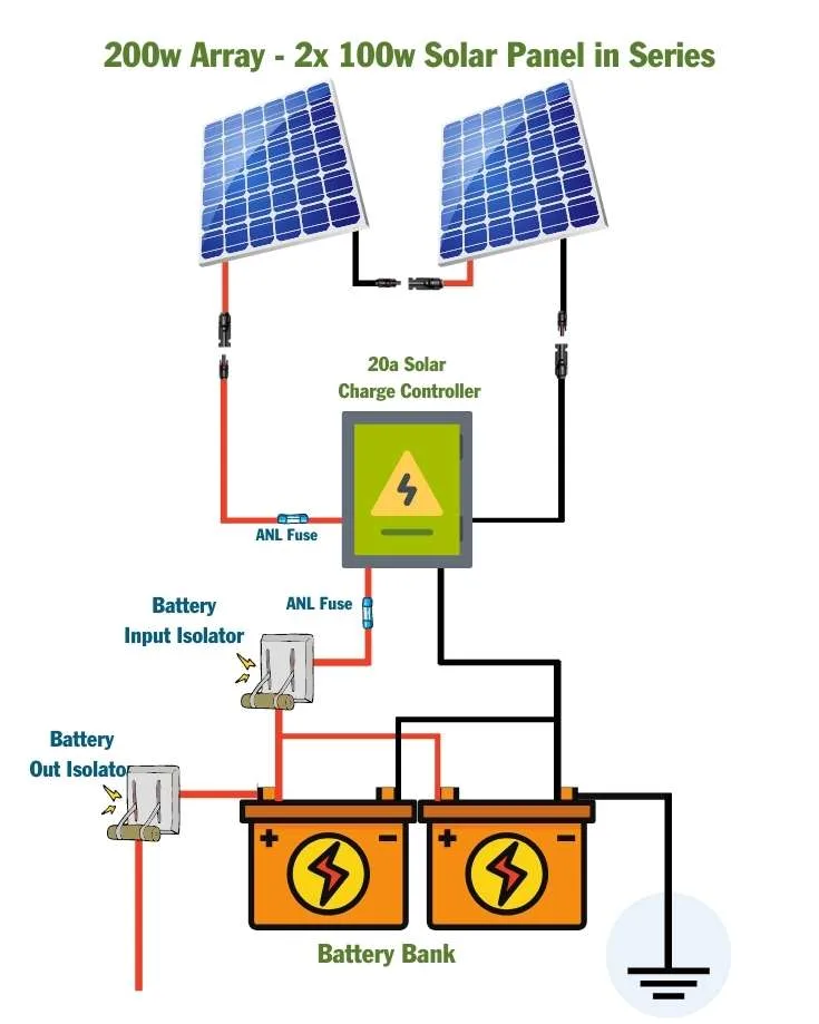
Image: mowgli-adventures.com
Key Elements of a Schematic Solar Panel Wiring Diagram
Schematic diagrams typically include the following elements:
- Solar Panels: Represented by a rectangle with arrows demonstrating the direction of current flow.
- Inverters: Shown as a square with the input and output terminals labelled.
- Batteries: Typically represented by a pair of parallel lines with + and – signs for polarity.
- Charge Controllers: Illustrated as a square with the charge current flow indicated.
- Circuit Breakers: Often depicted as a switch with an ‘O’ for open and a ‘C’ for closed.
- Wiring: Shown as lines with arrows indicating the direction of current flow.
Types of Solar Panel Wiring Diagrams
Series Wiring
In series wiring, solar panels are connected end-to-end, like a chain. This configuration allows for increased voltage but maintains the same current. Series wiring is generally used to increase the voltage output of the system, which is essential for maximizing power generation efficiency in certain applications.
Parallel Wiring
Parallel wiring connects solar panels side-by-side, like branches on a tree. In parallel wiring, the current increases, but the voltage stays the same. This configuration is preferred when higher current is needed, such as in applications with multiple appliances operating simultaneously.
Series-Parallel Wiring
Series-parallel wiring combines elements of both series and parallel configurations. This method involves connecting multiple sets of solar panels in series, and then connecting these series string in parallel. This approach provides flexibility in adjusting both voltage and current to optimize system performance.
Reading and Interpreting Schematic Solar Panel Wiring Diagrams
While schematic diagrams might initially appear daunting, understanding their structure and symbols is not as complex as it might seem. Here are some tips to help you navigate your way through these diagrams:
- Start with the Panels: Locate the solar panels represented by rectangles with arrows. The direction of the arrows shows the direction of current flow.
- Follow the Path: Trace the wiring lines from the panels to the inverter, battery, and other components. The arrows indicate how the current flows.
- Learn the Symbols: Familiarize yourself with standard symbols for components like inverters, charge controllers, circuit breakers, and fuses.
- Look for Labels: Diagrams often include labels for voltage levels, current ratings, and other important information.
- Reference the Key: Many diagrams include a key or legend that explains the meanings of different symbols.
Using Schematic Solar Panel Wiring Diagrams for DIY Projects
If you’re venturing into a DIY solar installation, having a clear understanding of schematic diagrams is essential for success. They’ll guide you through the wiring process, ensuring proper connections and minimizing the risk of errors. For safety, always get professional guidance and review your work with an experienced electrician.
Tips for Using and Understanding Schematic Solar Panel Wiring Diagrams
Here are some practical tips to make your journey with schematic diagrams smoother:
- Start Simple: Begin with basic diagrams and gradually work your way up to more complex examples.
- Practice Makes Perfect: Try tracing the current flow in multiple diagrams to develop a strong understanding of how they work.
- Don’t Be Afraid to Ask Questions: If you’re unsure about something, don’t hesitate to consult online resources, forums, or professionals for clarification.
- Utilize Online Resources: Many online resources offer interactive schematic diagrams and explanations that can enhance your learning experience.
- Focus on the Flow: Remember, the core purpose of a schematic diagram is to visualize the electrical current flow within the system.
FAQ about Schematic Solar Panel Wiring Diagrams
Q: What is the difference between a schematic diagram and a wiring diagram?
A: A schematic diagram focuses on the electrical flow and interactions within a system, using standardized symbols, while a wiring diagram provides a detailed visual representation of physical connections and components, often including measurements and specifications for physical installation.
Q: Can I create my own schematic solar panel wiring diagram?
A: While it’s possible to create basic diagrams, designing complex systems requires knowledge of electrical engineering principles and safety standards. Consult with a qualified professional for any significant solar system design or installation projects.
Q: Is it safe to work with electrical systems?
A: Solar systems operate with DC power, and while generally safer than AC, working with any electrical system requires caution and knowledge of safety protocols. Always disconnect the system before working on any components.
Schematic Solar Panel Wiring Diagram Pdf
Conclusion
Schematic solar panel wiring diagrams are essential tools for understanding and building solar power systems. By familiarizing yourself with their components, symbols, and interpretations, you’ll have a solid foundation for tackling solar projects and troubleshooting potential issues. Whether you’re a beginner or an experienced enthusiast, mastering these diagrams will empower you to harness the power of the sun and contribute to a brighter, more sustainable future.
Are you interested in learning more about solar energy and schematic diagrams? What other questions do you have about solar panel wiring?


